
MECHANICAL CONSIDERATIONS
An insulator is a mechanical support. After the mechanical aspects of a design have been finalized, electrical characteristics are added. If the insulator doesn’t keep your line in the air, all electrical characteristics in the world mean nothing. Mechanical characteristics are so important to the functioning of an insulator that they’re the one commonality in the marking of all insulator. Another question to take in account is the consequences of a mechanical failure: Loss of leakage distance only or cable fall. This depend of the design of the insulator. IEC 60797 stablish the mechanical residual test methods and acceptance criteria for glass or porcelain string insulators with the dielectric part breakage.
The use must determine the maximum loading that the line will ever apply to its insulator, including conductor weight, hardware weight, ice and wing loading, and other overload factors.
Suspension insulators are rated in terms of their Specified Mechanical Load (SML). Most manufacturers recommend that you never load the insulator to more than 50% of the Specified Mechanical Load (SML). The SML rating is a guaranteed minimum ultimate strength rating. Each batch of insulators produced is sampled for mechanical strength and all samples must meet or exceed the stated SML value and the statistical criteria. The routine test load is the proof load applied to each unit and also the maximum load that the insulator should ever see in service.
IEC 60383-1 & IEC 61109 stablish the mechanical test methods and acceptance criteria for Ceramic or glass insulators units and Composite insulators respectively.
ELECTRICAL CONSIDERATIONS
The electrical characteristics of the insulator are imparted by the air around it. This is principally defined by the arcing distance of the insulator defined as “shortest distance in the air external to the insulator between the metallic parts which normally have the operating voltage between them”.
The impulse withstand/flashover characteristics and dry power frequency characteristics are all based upon the dry arcing distance.
Some would argue that the wet power frequency withstand/ flashover characteristics are determined by leakage distance, but that argument only holds within a narrow band of leakage distances. Leakage distance plays a role, but only as a contributing factor.
IEC 60071-1 recommend the withstand voltages associated with the highest voltage for the equipment
TECHNIQUES FOR SELECTION AND DIMENSIONING OF HIGH VOLTAGE INSULATORS FOR USE IN POLLUTED AREAS
Last edition of series IEC TS 60815 has developed new techniques for the selection and dimensioning of high voltage insulators. It enables, after an established process, to determinate the most efficient insulation. The technical specification recommends three approaches to select suitable insulators based on system requirement and environmental conditions:
- Approach 1: Use past experience
- Approach 2: Measure and test
- Approach 3: Measure and design
The applicability of each approach depends on available data, time and economics involved in the project.
Some of the parameters required for these approaches are mentioned on the following sub-chapter:
Determination of the reference Unified Specific Creepage Distance (RUSCD)
Figure 1 shows the relation between site pollution severity (SPS) class and RUSCD (reference unified specific creepage distance) for insulators. The bars are preferred values representative of a minimum requirement for each class and are given for use with approach 3 (measured and design) of the IEC/TS 60815-1.
If the site pollution severities (SPS) are available, it is recommended to take a RUSCD (reference unified specific creepage distance) which corresponds to the position of the site pollution severity (SPS) measurements within the class by following the curve in Figure 1.
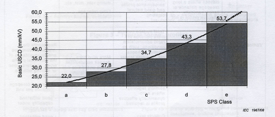
Figure 1: RUSCD a function of SPS class
|
Basic USCD (mm/kV*) * r.m.s. value of the highest operating |
Site pollution severity (SPS) classes: a: Very light b: Light c: Medium d: Heavy e: Very heavy |
For Type A pollution (inland, desert or industrially polluted areas), SPS is calculated from ESDD/NSDD values.
For Type B pollution (coastal areas where salt water or conductive fog is deposited onto the insulator surface), SPS is calculated from SES (site equivalent salinity)
Choice of profile – glass and ceramic insulators
Different types of insulator and even different positions of the same insulator type may accumulate pollution at different rates in the same environment. In addition, variations in the nature of the pollutant may make some shapes of insulator more effective than others.
IEC TS 60815-2 – Table 1 below shows a brief summary of the principal advantages and disadvantages of the main profile types with respect to pollution performance.
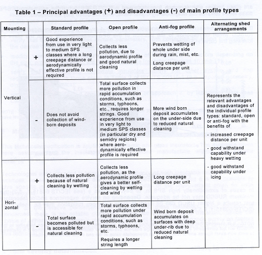
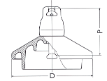
Standard profile
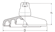
Aerodynamic or open profiles
Antipollution profiles
Profile suitability – glass and ceramic insulators
IEC TS 60815-2 – Tables 2 & 3 give simple merit values for ceramic and glass insulator profiles. Table 2 give the profile suitability, relative to standard profile assuming the same creepage distance per unit or string, Table 3 assuming the same insulating length.
Below tables show a brief summary of the principal advantages and disadvantages of the main profile types with respect to pollution performance.
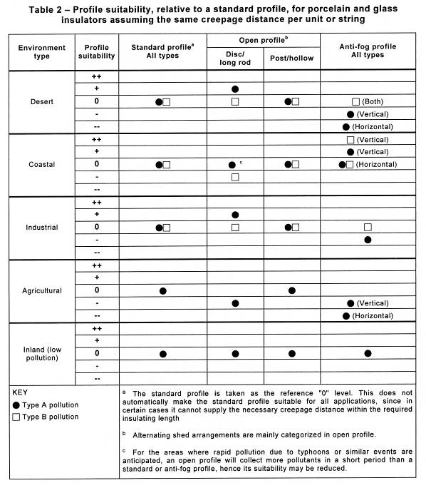
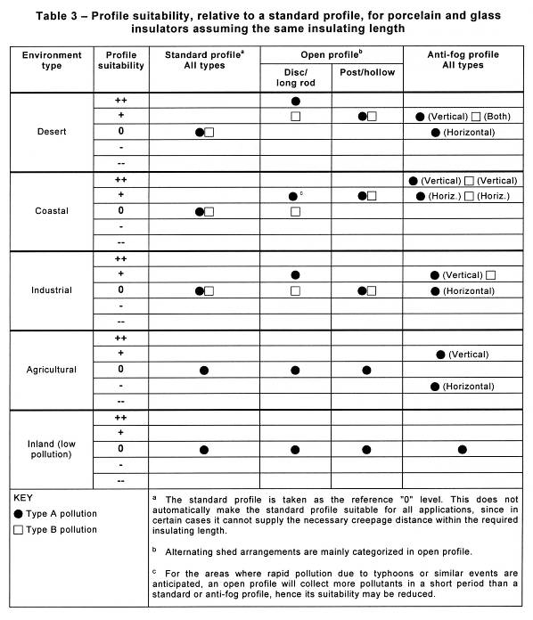
Type A pollution: Solid pollution with non-soluble components.
Type B pollution: Liquid electrolytes with very little or no non-soluble components.
Also IEC TS 60815-2 give profiles parameters to take in account:
- Alternating sheds and shed overhang;
- Spacing versus shed overhang;
- Minimum distance between sheds;
- Creepage distance versus clearances;
- Shed angle;
- Creepage factor.
Polymer profile and parameter
IEC TS 60815-3 – Chapters 8 & 9 give recommendations for polymer insulators profiles and parameter to take in account:
- Alternating sheds and shed overhang;
- Spacing versus shed overhang;
- Minimum distance between sheds;
- Creepage distance versus clearances;
- Shed angle;
- Creepage factor.
Pollution tests standards
Pollution tests on glass and porcelain insulators on a laboratory can be carried out for two main objectives:
- To obtain information about the pollution performance of insulators (comparison of different insulator types/profiles)
- To check the performance in a configuration as close as possible to the in-service one.
IEC 60507 prescribe procedures for artificial pollution tests applicable to ceramic and glass insulators for overhead lines.
Two categories of pollution test methods are recommended for standards tests:
- Salt fog method in which the insulators is subjected to a defined ambient pollution:
- Solid layer method in which a fairly uniform layer of a defined solid pollution is deposited on the insulators surface.
This standardized laboratory pollution test methods are not applicable for composite (polymeric) or RTV-coated insulators. A proposal for a test method for artificially polluted composite insulators is covered by the recent CIGRE TB 555: “Artificial Pollution Test for Polymer Insulators”.
In the case of naturally polluted insulators removed from the service a recent CIGRE TB 691 (WG D1.44), “Pollution Test of Naturally and Artificially contaminated insulators” summarizes the recent experience with so-called rapid flashover test methods:
- Rapid flashover Test (RFO, based on IEC 60507 solid layer test).
- Quick flashover (QF, based on IEC 60507 salt fog test).
Both tests can be applied for both ceramic (glass and porcelain) and composite insulators for both AC and DC.
The objective of these tests is a need for reliable diagnostic of naturally polluted insulators to evaluate their residual dielectric strength and also a general trend to make testing more cost-effective and time-efficient, even for the case of artificially polluted insulators.
A reduction of performance can be due to pollution in case of ceramic insulators or due to a combination of pollution and ageing in case of polymeric insulators. In both case cases the residual pollution strength should be quantified in terms of a flashover voltage, not a withstand voltage; because the withstand voltage does not provide the user by the information about the probability for flashover or standard deviation of flashover voltage.
Insulator testing stations
Sometime, the combination of the many variable environmental parameters which influence an insulator’s behaviour over its lifetime are difficult to artificially simulate and, moreover, to accelerate. The validity of laboratory tests is thus often questions as the procedures adopted may not take into account significant factors which would be encountered in service or they may over-emphasise others.
The evaluation of insulator performance in naturally polluted outdoor test stations is becoming more important and popular. Although involving a longer test duration, and still requiring care in the correct interpretation of the test data, the results tend to be accepted with more confidence.
Outdoor test stations is also a good tool for new insulation technologies in which there is as yet no technical or normative specification for its testing or characterization.
CIGRE Technical Brochure No. 333, 2007 “Guide for the establishment of naturally polluted insulator testing stations” serve as a general guide for the establishment of natural test stations which will facilitate the overall comparison of various insulators designs, the explorations of particular aspects of insulator performance and/or the selections of the most appropriate insulation for a particular application. It is relates specifically to insulators intended for use under AC conditions but aspects are applicable to DC stations as well.
Typical test aims may be one or more of the following:
- To compare the performance of insulators of different design.
- To compare the performance of insulators from different manufacturers.
- To dimension insulators for a particular environment or application.
- To examine the behaviour of insulators of different dielectric materials.
- To compare the performance of insulators in different orientations.
- To explore the affects of specific parameters such as profile geometries or insulators diameters.
- To identify possible weaknesses or failure mechanisms of an insulator design.
- To estimate the life expectancy of various insulators.
- To serve as a qualification test for potential suppliers.
- To establish the effectiveness and life of insulator treatments such as washing, greasing, silicone rubber coating, shed extenders, etc.
- To assess the performance of other outdoor equipment insulation such as transformer bushings, surge arresters, cable terminations, etc..
The severity of the pollution and the prevailing climate must be examined and should be representative of conditions found on the system. As is the case for laboratory tests, an over-acceleration of the ambient stresses can produce misleading results. Contamination severity assessment by means of ESSD and NSDD measurements and/or directional dust deposit gauges should be undertaken to ensure that an appropriate site is selected.
Insulator test stations have a wide range of size and sophistication and may be categorized as:
- Research station;
- Simplified, on-line station;
- In service Test Structure;
- Mobile insulator Test Station.


Photo 1: Permanent insulator research station at Martigues (France) and examples of Verescence La Granja Insulators tests

Photo 2: On-line insulator test station

Photo 3: In-service insulator test structure

Photo 4: Mobile insulator test stations
Leakage current activity (include number of flashovers experienced), climatic effects and pollution severity are usually monitored. In addition, the performance of the test samples should be judged by a regular inspection of the insulators: Close visual examination of the surface; an assessment of the hydrophobicity of the dielectric material and the viewing of electrical activity.
OTHER PROBLEMS ARISING FROM POLLUTION: INSULATORS CORROSION
Insulators fittings corrosion mechanism
Insulators corrosion occurs if the surface of the insulators is polluted, and in the presence of humidity.
When the insulators surface is covered by deposit wet pollution, leakage currents start. Its amplitude is a function of the degree of pollution (the amount of soluble salts).
Polluted and wet insulators energized with AC voltage display a biased leakage current having a DC component that causes electrolytic corrosion of the pins.
Leakage currents effects are even more harmful when the frequency and duration of wet periods are high (humid tropical climate) and also when pollution finds a hygroscopic surface (Hence the importance of inert contaminants that absorb or retain humidity).
This corrosion is most important on DC voltage than AC voltage for same site, due to current unidirectional and electrostatic phenomena that cause the most important pollution deposition formation.
For insulators, dominant electrolytic corrosion effects add to those of atmospheric corrosion and those due to the formation of oxidising agents caused by the presence of arcs near fittings. These last ones can be initiated and maintained during periods of humidification and drying that precedes and succeeds in critical conditions or when the insulator is more humid. Protection field dispatcher accessories can be beneficial to limit these phenomena of humidification and drying periods which are a factor of acceleration of the insulator fittings corrosion for those pieces that are more electrically forced.
Corrosion phenomena result in:
- an attack of the galvanisation.
- an attack of the internal steel structure with the formation of a conductive rust deposit that can flow on the dielectric.
The most severe corrosion cases occur especially in the tropical areas very near to the sea or marine pollution and areas where the pollution by dust accumulation happen for long periods without rain, plus the high environment humidity.
Phenomena linked to corrosion of metal parts
Insulators fittings corrosion may have the following effects:
- To affect the mechanical resistance of the insulator: This applies particularly to the pin of the insulator when the section of the corroded part becomes reduced (example: reduction of the diameter of the pin).
- To affect the electrical resistance due to the formation of a deposit of rust on the insulating surface. This deposit may also cause damage in the insulating part due to a concentration of electric field around this new electrode.
- To cause the breakage of the dielectric due to the expansion of the pin corroded. This phenomenon is specific for porcelain cap and pin insulators.
Remedies to improve the resistance to corrosion on insulators
Metal parts protections have been developed to avoid or delay corrosion phenomena.

Photo 5: Example of insulators with zinc sleeves and reinforced galvanization installed in Canary Islands
They consist of reinforced galvanized fittings and of a sacrificial zinc sleeve protection.
- Reinforced galvanized fittings: IEC-60383-1 Chapter 26 standardize the minimum average coating mass for the metal fitting of the insulators: 600g/m2 (85µm). Anyway, this value can increase until 140µm for insulators to be install on very high corrosion area. This permit increase the estimated end of life.
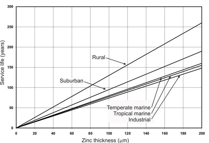
Fig. 2: Zinc thickness vs service live
- The zinc sleeve is galvanically positive and has a large potential difference from iron. It works like as a sacrificial electrode at the cement boundary where the current flows. The zinc sleeve is free from accumulation of corrosive products.

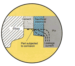
Fig. 3: Detail of leakage current on insulator
IEC-61365 specifies the minimum requirements for the zinc sleeve; anyway, it can be improved to increase it behaviour.

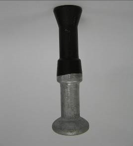
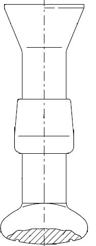
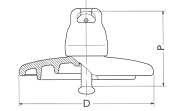
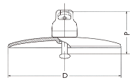
Fig. 4: Drawing and photo of a pin with zinc sleeve
Also IEC-61365 specifies test method for the zinc sleeve control. Future work of normalization would have to be to include the zinc sleeve requirements and the tests methods on the IEC-60383-1 (for a.c. lines)
OPERATION PARAMETERS
The main objective of the overhead line maintenance policy in an electric company is to maintain the number of fault outages at reasonable values. A Data Base with the principal information of the insulation is an efficiency tool for the evaluation of performance. The information that this database should contain is:
- Type / Sub-type of string;
- Type of insulation: Glass, ceramic, composite, coated glass, etc..
- Sub-type of insulator: Standard profile, pollution profile…
- Number of insulator per string;
- Manufacturer of the insulation;
- Insulator trazability data (Production order, production date…)
- Standard;
- Installation year;
- Silicone manufacture / applicator;
- Estimated end of life
- Degradation environment: Normal, hard and very hard.
Several maintenance indicators are habitual used by the utilities:
- Number of faults
- Insulator breakage rate
- Washing frequency
Also numerous methods of maintenance procedures are well-known by the utilities:
- Aerial inspection
- Patrol inspection
- HD recording
- Infrared inspection
The evolution of maintenance indicators together with the results of inspections linked with the data base of the line help both the decision making regarding the maintenance or replacement of the insulation and the valuation / comparison of the different types of materials, profiles and manufacturers quality.
Estimated end of life – glass and ceramic insulators
Insulators are high-technology products expected to work with high reliability over a long period of time. A great number of successfully balanced design parameter, analyzed in the previous chapters, choice of material as well as mastering of manufacturing processes are required to ensure this high long term reliability.
An insulator comes to the end of its working life either when it fails mechanically, flashover at unacceptably high frequency or gives evidence of deterioration to a condition likely to lower its factor of safety in service. All insulators are affected to some extend by impact, cycling but thermal and mechanical, deterioration from weathering and electrothermal causes, flexure and torsion, ionic motion, corrosion and dement growth.
Determinate the exactly time to replace if it necessary is important to optimise the cost of maintenance. There are a fairly large number of degradation modes. Some modes are easily detectable by visual inspection other, especially for porcelain insulators, need sophisticated methods. Degradation modes causes by easily detectable mechanism like slip of metal fitting, pin corrosion or surface erosion are considered to be reason for replacement of insulators.
CIGRE has established a test procedure to determinate the state of cap and pin and long-rod insulators and to decide on the safe time for their replacement: “Guide for the assessment of old cap and pin and long-rod transmission line insulators made of porcelain or glass: What to check and when to replace”. CIGRE Technical Brochure No. 306, 2006.
This document stablishes a testing sequence with a number of non-destructive tests as visual tests (e.g. degree of corrosion) as well as dimension and thermal and the combined thermal-mechanical tests. This first series of tests is followed by destructive mechanical tests. A probability diagram based on normal distribution is used to analyse the failing load test results. With the probability (risk) for failure on the ordinate and the failing load on the abscissa, the failing load characteristics are represented as straight lines. In that way changes in strength become easily visible.
To help the user, the document includes a number of typical cases of analysis of test result called “Reference Scenarios”. They are useful for the assessment of the present condition of the insulator

Fig. 5: Example: Reference scenario F1
The failing load characteristics are represented by:
- A dashed line for the insulators sample tested when new.
- A solid line for the insulators as-received from the line.
- A dashed/dotted line for the insulators which have been submitted to the Thermal-mechanical test (TMP-test)
The SFL (specified failing load) is marked with a solid vertical line.
For the example of ”Reference scenario F1” the reductions in strength shown in this example diagram are not representative of good quality products. Age and TMP-test have only negligible influence on good products.
Estimated end of life – Composite insulators
Parallel to this document, another Technical Brochure published by CIGRE assist to evaluate the technical conditions of aged, old or failed composite insulators: “Guide for the assessment of composite Insulators in the laboratory after their removal from service”. CIGRE Technical Brochure No. 481. Different methods, philosophies and tools are descripted which enable a conclusion regarding the residual life-time of composite insulators of the same age and design family. The document also give indications of work for the case of an investigation a failure or a unit recognized as high risk and evaluation of units for research.
It is based on a recommended sequence of testing on samples taken out different stress zones of the line.
Fig. 6: Recommended sequence of testing
CONCLUSION
The selection of the insulator type is not a simple job, especially if the insulator will be install in a high polluted area.
Numerous documentations (IEC Standards, CIGRE Technical Brochure…) are available to help on the selection of the most appropriate insulator, for monitoring the behavior in operation and for the determination of the finite insulator life.
Different solutions are available to improve the insulator performance on high corrosion areas.
Several factors must be taken in account on the insulator type selection:
- More effective design/material;
- Maintenance costs: Inspection cost, clean cost, replacement costs, …
- Expected service breakage rate to be guarantee/certify by the supplier;
- Severity of consequences in case of failure (mechanical breakage, electrical failure,…);
- Expected end of life.
BIBLIOGRAPHY
[1] IEC 60050-471: International Electrotechnical Vocabulary. Part 471: Insulators
[2] IEC 60071-1: Insulation co-ordination – Part 1: Definitions, principles and rules
[3] IEC 60575: Artificial pollution tests on high-voltage ceramic glass insulators to be used on a.c. systems.
[4] IEC 60797: Residual strength of string insulator units of glass or ceramic material for overhead lines after mechanical damage of the dielectric.
[5] IEC-60383-1: Insulators for overhead lines with a nominal voltage above 1 000V: Ceramic or glass insulators units for a.c. systems – Definitions, test methods and acceptance criteria
[6] IEC/TS 60815-1: Selection and dimensioning of high-voltage insulators intended for use in polluted condition – Part 1: Definitions, information and general principles
[7] IEC/TS 60815-2: Selection and dimensioning of high-voltage insulators indented for use in polluted condition – Part 2: Ceramic and glass insulators for a.c. systems
[8] IEC/TS 60815-3: Selection and dimensioning of high-voltage insulators indented for use in polluted condition – Part 3: Polymer insulators for a.c. systems
[9] IEC 61109: Insulators for overhead lines – Composite suspensions and tension insulators for a.c. systems with a nominal voltage greater than 1 000 V – Definitions, test methods and acceptance criteria
[10] IEC-61365: Insulators for overhead lines with a nominal voltage above 1 000V: Ceramic or glass insulators units for d.c. systems – Definitions, test methods and acceptance criteria
[11] I. Gutman, Wallace Vosloo, “Development of Time-and Cost-Effective Pollution Test Methods Applicable for Difference Station Insulation Option”. IEEE Vol. 21, No. 6. TDEI submitted 2014.
[12] M. Marzinotto, J-M. George, S. Prat, C. Lumb, F. Virlogeux, I. Gutman, and J. Lundengard, “Field Experience and Laboratory Investigation of glass Insulators Having a Factory-Applied Silicone Coating”, TDEI submitted 2014.
[13] I. Gutman, J. Shamsujjoha, C. Lumb, J-M. George, and S. Roude: “Investigation of Rapid flashover solid layer pollution testing as an alternative to current standard method”, IEEE ISEI-2012, paper 17 pp.73-77
[14] CIGRE Task Force 33.04.07, “Natural and artificial ageing and pollution testing of polymeric insulators” CIGRE Technical Brochure No. 142, 1999
[15] CIGRE WG B2.03, “Guide for the assessment of old cap and pin and long-rod transmission line insulators made of porcelain or glass: What to check and when to replace”. CIGRE Technical Brochure No. 306, 2006
[16] CIGRE WG B2.03, “Guide for the establishment of naturally polluted insulator testing stations” CIGRE Technical Brochure No. 333, 2007
[17] CIGRE WG B2.21, “Guide for the assessment of composite Insulators in the laboratory after their removal from service”. CIGRE Technical Brochure No. 481, 2011
[18] CIGRE WG D1.44, “Pollution Test of Naturally and Artificially contaminated insulators” CIGRE Technical Brochure No. 691, 2017
[19] Javier GARCIA /Philippe Platteau. Glass insulators in polluted environment: design, test, experiences and benchmarking with other materials. Cigre regional meeting outdoor insulation. Tunisia, 2010
[20] R. García Fernández, M.A. Perez Louzao, I. Serrano “REE’s insulator global maintenance policy”, CIGRE 2014; B2-206.
Deja tu comentario